I'm Michel Rouzic, the sole person behind Photosounder, SplineEQ and Spiral. The name of my first program became the name of my "company" because I couldn't think of a company name plus I was already using this domain name. I hate naming things, I tried to come up with a company name by starting with 'Michel Rouzic Software', taking the first half of each word then putting it all together but that gave me Microusoft, and that's just one letter away from Microsoft. And Microsoft? What kind of a name is that for a company!? It might as well be called Small & Flaccid! Think about it!!
This page is all about some of the other things I've done either besides or as part of my 3 main projects.
- rouziclib
- GTA: Vice City - Michel edition
- Sponge Blob Tennis
- sRGB - Or how I resent you for not understanding it
- 10-bit square root pixels - An advantageous texture format
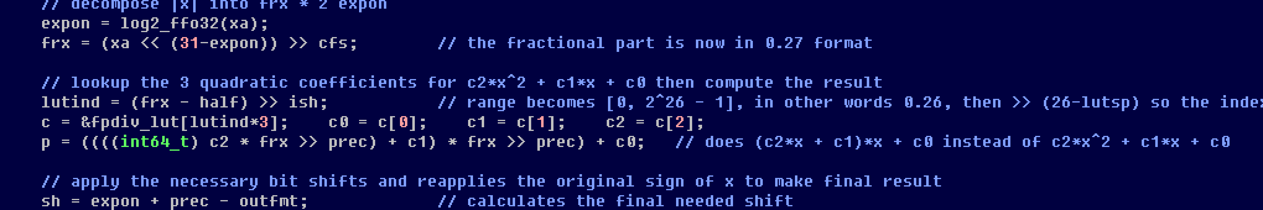
- Polynomial lookup table-based approximations of mathematical functions
- Flat-top linear filtering for non-integer image scaling
- Contact
Rouziclib is my personal open source library of code that is shared between my different projects. I made it when it became impossible to maintain several copies of the same code in several projects. Now when I update one function in rouziclib all my projects benefit from it.
Rouziclib contains a lot of the algorithms described below, and a lot of the graphics and mathematics code used in SplineEQ and Spiral, such as code for drawing antialiased lines, circles, frames and gradients, the perceptual colour space used by Spiral or the fast approximations of mathematical functions that make Spiral faster than it would otherwise be.
If you're a developer with code of your own that you reuse across projects I believe that like me you should make a library out of it and consider sharing the sources for the benefit of all.
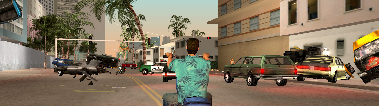
5 years ago I started my own fork of GTA: Vice City based on a decompiled version of the original game. I fixed some things that really needed fixing but also added pretty wild cheats and features which are listed and illustrated in detail on that GitHub page. Try it.
Driving and adjusting the camera with a MIDI controller in my version of GTA: Vice City
The animation.
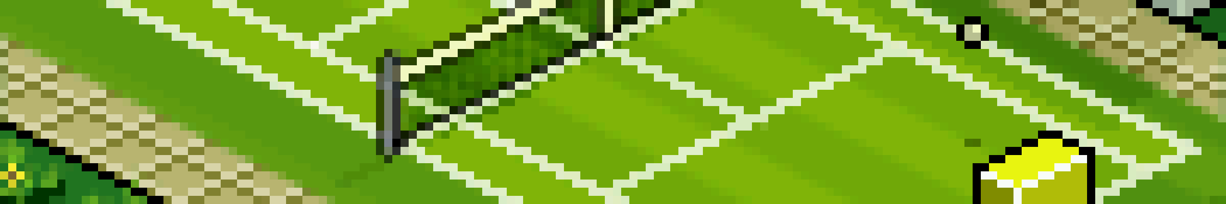
The game.
It has realistic physics (realistic gravity, bounce and air friction), the players are not sprites, they're physical blobs that change shape depending on what happens to them, the graphics and fixed-point physics are so well optimised that I could still get 50 FPS by downclocking the GP2X from 200 MHz to 80 MHz, and it features a pretty good AI too. A year later I also added sound effects to the game. I drew those sound effects in pixel art to fit the general theme of the game and synthesised them using ARSS, Photosounder's command-line precursor.
A pixel art game needs pixel art sounds too.
By default you would be the player on the right side, however you can toggle AI control for any of the players at any time, so you can change sides, play with a friend (it was achieved by having each player hold a side of the GP2X console, a bit awkward but it worked) or just let the game play itself. You can try the Windows version of Sponge Blob Tennis, the source code is included, and now you can even try it in your browser! (use the keys 1 2 3 on the numpad, the other keys are U I to toggle AI control and X C V for the left player). And here's a random review.
I want to tell you about my greatest pet peeve, something that annoys me perhaps more than it should. It's something that you, personally, most likely despite believing the opposite, do not understand, even though you really should. I'm talking about gamma compression and how everybody, yourself included, mistakenly assumes that those familiar pixel colour values that range from 0 to 255 are linear. It's not just you, it's almost everybody else, photographers, designers, scientists, developers, even the guys who made Photoshop, or pretty much any image editor for that matter. That's right, the guys who made Photoshop don't seem to quite understand how pixels work.
Let me ask you this, if you have a grey pixel of RGB value 120, 120, 120, and you add it to another pixel of the same value (or just double the first value instead), what value should you get? 240, 240, 240? Wrong!
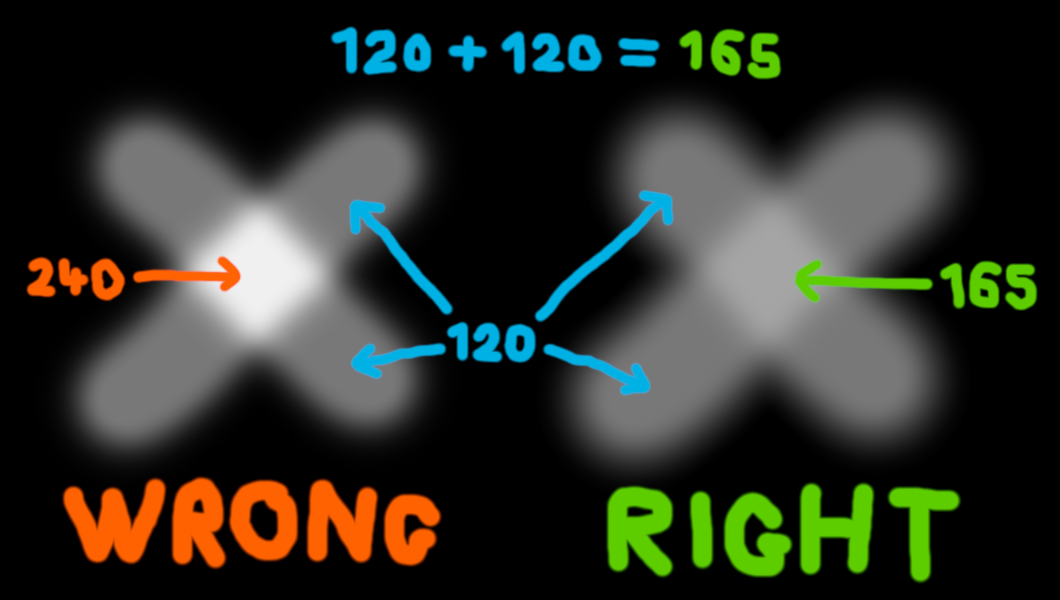
32 years of Photoshop layers and no one noticed the left cross looks a tad too bright?
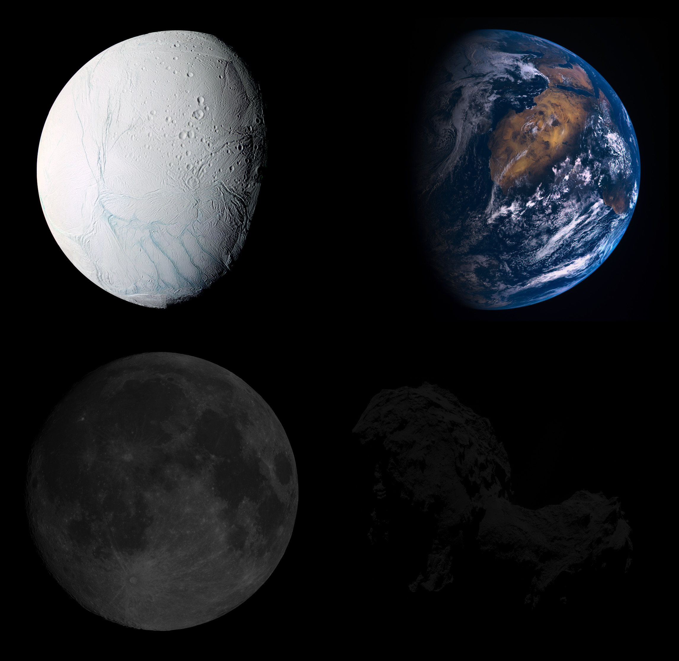
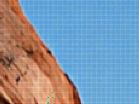
I care because that error is everywhere. It's in Photoshop (unless you use its 32-bit/channel mode, which last time I checked simply had a lot of functions missing), pretty much every other image editor, and pretty much every other software except 3D renderers (video games included) and some really expensive professional programs. Even colour spaces are based on the completely arbitrary sRGB compression. And the problem isn't just with adding two pixels, it affects antialiasing, blending and transparencies, even resizing or blurring is affected. For instance if you blur or shrink an image of a star field the result will be much darker than it should because when you average a star of let's say value 240 (0.871) with a background of 0 then instead of getting the physically correct average of 176 (0.436, which is 0.871/2) you get the much darker value of 120 (0.188). That's also how you can have pictures with thumbnails that look nothing like the full picture, as shown there.
Someone actually looked at this and thought
"yeah, that looks about right"...
If you're a developer and you do any kind of operations on pixels, please do the following. Use an internal representation for pixels that is linear, and use at least 12 bits per channel (I use a fixed point arithmetic format with 15 fractional bits and dithering as detailed here, so I get no banding on gradients) because you need an extra 4 bits to preserve the precision of the darkest pixels. When loading images convert them to your linear pixel format, and don't convert anything back to sRGB before you save an image or need to show it on screen. Simple lookup tables can do the job quickly both ways. Gamma-compressed sRGB is for storage in files and for displays. Always manipulate linear pixel values otherwise.
I also made a very simple online converter to switch back and forth between linear and sRGB which is quite handy if you need to calculate some values manually.
Now that you understand the importance of doing all operations on linearised pixels and that hopefully you understand that 8-bit per channel isn't quite enough even with gamma compression, we can consider practical aspects. So far I've used 3 different pixel formats, 8-bit sRGB, 15-bit (or 16-bit depending on how you count) fixed point linear format, and the gold standard of pixel formats which is 32-bit floating point linear format.
It doesn't get any better than the latter, it's linear, a native format (unlike say 16-bit floating point) to both CPUs and GPUs and in every language, high precision and it can handle out of range values which is very useful mostly when processing raw images as they can have negative values which are important to consider when scaling down or denoising. The big problem is that it's 4 times more data than 8-bit sRGB, so you're wasting a lot of time transfering textures in that format, and a lot of memory storing them. You could use 8-bit sRGB, however it's low precision which might show when you make mipmaps of a smooth gradient, and unless you want to use a lookup table (which you probably wouldn't want to on a GPU) then linearising takes a lot of math, including a very time-consuming pow(). We could choose a compromise between the two by using 16-bit fixed point format which is good and simple but still wasteful or 16-bit half floats which complicates the implementation significantly, and both are more wasteful than they need to be.

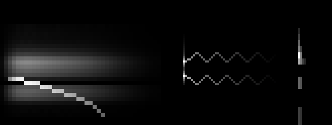
The square root and sRGB functions similarly offer higher precision in the darks (lower left corner).
But using more bits isn't the key. So far we only had a choice between sRGB and linear format, the former being advantageous by giving more precision in the darks but slow to convert and the latter requiring 4 extra bits per channel to obtain the same precision in the darks. I choose instead the best compromise, storing the square root of the linear value, in integer format of course. The reason why it's so advantageous is that while it's close to sRGB in terms of giving more precision in the darks, it couldn't be simpler or faster to linearise, all you have to do is multiply it by itself!
Let's say we start off with a linear value of 0.09, we take its square root 0.3, multiply it by 1023 (all this can be done very quickly when loading an 8-bit sRGB image using a sRGB to square root format lookup table) and store it as a 10-bit integer, 307. Then in order to use it we need to linearise it by multiplying it by itself, which gives us an integer value of 94,249 out of a maximum of 1023², and then we can either do what we need in integer form and then put the result back in square root format using an integer sqrt function like this one or even just sqrt() which could be faster, or convert it to float and multiply it by a float constant equal to 1023⁻² to bring it in the [0 , 1] range. Let's say for example that I want to average 4 pixel values into one to generate mipmaps, this must be done linearly but must be converted back to square root format, I can simply just do this: isqrt( p0*p0 + p1*p1 + p2*p2 + p3*p3 >> 2 );
In conclusion this format is:
- As compact as 8-bit sRGB as both take up 4 bytes per pixel whereas any other alternative is instantly 2 or 4 times more wasteful.
- High precision, which you might not need when displaying full resolution 8-bit sRGB images but do need when doing things like scaling down, so for instance a picture of a smooth blue sky might be a bit noisy at full resolution but very smooth and therefore susceptible to banding at lower sizes.
- Extremely fast to linearise as it only takes an integer multiplication and optionally a cast to float and a simple float multiplication as opposed to either applying the full sRGB formula which contains branching and a pow() or a lookup table.
- Somewhat fast and simple to store back, as it only takes a square root.
It is mainly intended to be used as an internal replacement for 8-bit sRGB so that you can load a picture, convert it to 10-bit square root format and then forget all about sRGB, then tile and mipmap it and send the tiles to the GPU as needed for displaying where every pixel will upon loading be linearised into a float vector.
In approximating mathematical functions on computers there are three main factors to balance: speed, precision and memory usage. Approximations using simple lookup tables (LUTs) that contain precalculated values for the function to approximate are typically quite fast but not very precise and take up a lot of memory. They also become slower as the table gets larger due to the inability to contain the whole table at the lowest cache levels. Precision can be improved by linearly interpolating two neighbouring LUT entries at the cost of speed. Another approach is to approximate a function using polynomials. Polynomial approximations have the advantage of requiring very little memory, however they can only improve in precision by increasing the polynomial order which both slows down the computation tremendously and limits the maximum precision since an increase in operations for the computation of a single value increases the rounding error with every operation.
There is however a very little-known (I haven't found anything about it anywhere, if you have let me know) way to combine the advantages of lookup tables and polynomial approximations. It is simply to have a lookup table that contains the coefficients for a quadratic polynomial or higher (a sextic polynomial is fine too), a polynomial which would accurately approximate only a small subrange of the whole range to approximate, with all the elements of the LUT together effectively approximating the whole desired range. The advantages are many, a quadratic polynomial can be computed quickly, unlike with linearly interpolated LUTs there is no interpolation between two values to perform, precision increases by up to a factor of 8 for every doubling of the LUT's size as opposed to 4 for interpolated LUTs and 2 for plain LUTs, high precision can be achieved with small tables. I typically use tables that represent only 128 segments and therefore take up a very few kilobytes, this allows the LUTs for several functions to fit inside in a CPU core's 16 to 32 kB Level 1 cache.

The cosine and its quadratic approximation over the blue range [0.375 , 0.4375]
with c2 = 16.35989, c1 = -16.76637 and c0 = 3.27985.

The error curve between the approximated function
and its approximation over the blue range.
The result is found by obtaining from the LUT the three quadratic coefficients c0, c1 and c2 so that f(x) = (c2x + c1) x + c0. Those coefficients should be obtained from the LUT at an index typically derived from either the most significant bits of x if x is an integer or fixed-point arithmetic number, or if x is a floating point number from the most significant bits of the mantissa or even a combination of the lower bits of the exponent and the upper bits of the mantissa, depending on the range covered by the LUT. The top of the mantissa is of course best suited for ranges such as x = [0.5 , 1.0[ or [1.0 , 2.0[, but simply adding 1 to x at the start of the function can make it suitable for a x = [0.0 , 1.0[ range.
A small detail remains which is how to compute the coefficients in the LUT in the first place, or in other words how to get a quadratic fit for a segment of the function to approximate. I choose not to minimise the averaged squared error but rather to minimise the maximum error, since the maximum error is what matters to me most when evaluating the precision of an approximation. I do this by first calculating c2 using the difference of the point in the middle of the subrange (delimited by start and end) between its f(x) value and the average of f(start) and f(end) then working from f(x) - c2x² to find c1 and c0, like so:
    void find_quadratic_fit(double (*f)(double), double start, double end, double *c0p, double *c1p, double *c2p)
    {
            double c0, c1, c2, middle, p1, p2, height2, width2;

            c1 = (f(end) - f(start)) / (end - start);

            middle = (end+start) * 0.5;
            height2 = (f(end)-c1*end) - (f(middle)-c1*middle);
            width2 = end - middle;
            c2 = height2 / (width2*width2);

            p1 = 0.75*(end-start) + start;
            p2 = 0.25*(end-start) + start;
            c1 = ((f(p1)-c2*p1*p1) - (f(start)-c2*start*start)) / (p1-start);
            c1 += ((f(end)-c2*end*end) - (f(p2)-c2*p2*p2)) / (end-p2);
            c1 *= 0.5;

            c0 = ((f(end)-((c2*end + c1)*end)) + (f(start)-((c2*start + c1)*start))) * 0.5;

            *c0p = c0;
            *c1p = c1;
            *c2p = c2;
    }
With that approach the error curve between the approximated function and the approximation should be S shaped with peaks of equal absolute height at the start, the end, one quarter and three quarters of the segment.
You can find a few examples of that approach being used in rouziclib with fixed-point arithmetic examples for atan2, cos, division (the reciprocal function) and floating point examples for log2, exp2, sqrt and a high precision quintic cos.
This is what those peaks from a naive non-integer bilinear filtering look like.
Linear filtering at varying downscaling ratios. The spikes in the sum are undesirable.

My solution: flat-top linear filtering. The sum is desirably much smoother.
Thankfully there's a simple modification we can bring to that triangle-shaped convolution kernel, and that's giving it a flat top. So now to calculate the weight of a pixel we need to use two of the following three parameters: the height of the flat top top, the position of the end of the flat top knee and the slope that comes after that knee, slope. For a scaling ratio of n and an absolute distance from the pixel of x, the weight can either be obtained by making x be at least the value of knee and then finding the height on the slope, or finding the height on the slope first then making sure it's not higher than top, and of course as always make sure to only look for weights in the [-n , n] range.
	x = fabs(x);

	// first method
	x = max(x, knee);	// this makes x be at least knee
	y = slope * (x-n);

	// second method
	y = slope * (x-n);
	y = min(y, top);	// this makes y (the weight) be no more than top
And here's how we calculate those 3 parameters, which only needs to be done once for a given scaling ratio of course.
	knee = 0.5 - fabs(fmod(n, 1.) - 0.5);		// the knee position ping pongs within [0 , 0.5] depending on n
	midpoint = floor(n+0.5);			// the mid-point of the current trough segment
	trough = 2.*midpoint - midpoint*midpoint/n;	// the height of the trough
	top = (1. - knee/n) / trough;			// the height of the flat top
	slope = -top / (n-knee);			// and the most important, the slope
So knee is easy to compute, which might make the first method more advantageous in a GPGPU context as it might be quicker to calculate it every time than to read it from global memory. It's a bit hard to explain how it's all computed, so I guess you shouldn't worry about it and just copy my code. Another solution to the same problem I used before this was to make a sum of every weight for each output pixel, then divide the pixel values by the sum of the weights, which is a less elegant solution as it adds more math for each pixel and does undesirable things on the edges of the image as the sum of the weights goes towards zero.
The purpose of this is for me to display images on screen using tiled mipmaps, the mipmap level right above the needed on-screen dimensions is selected, then displayed with the right dimensions using this flat top linear filtering. Note that this is good for every downscaling factor, but not for upscaling, for this you need to switch back to simple bilinear interpolation.
You can contact me by e-mail at